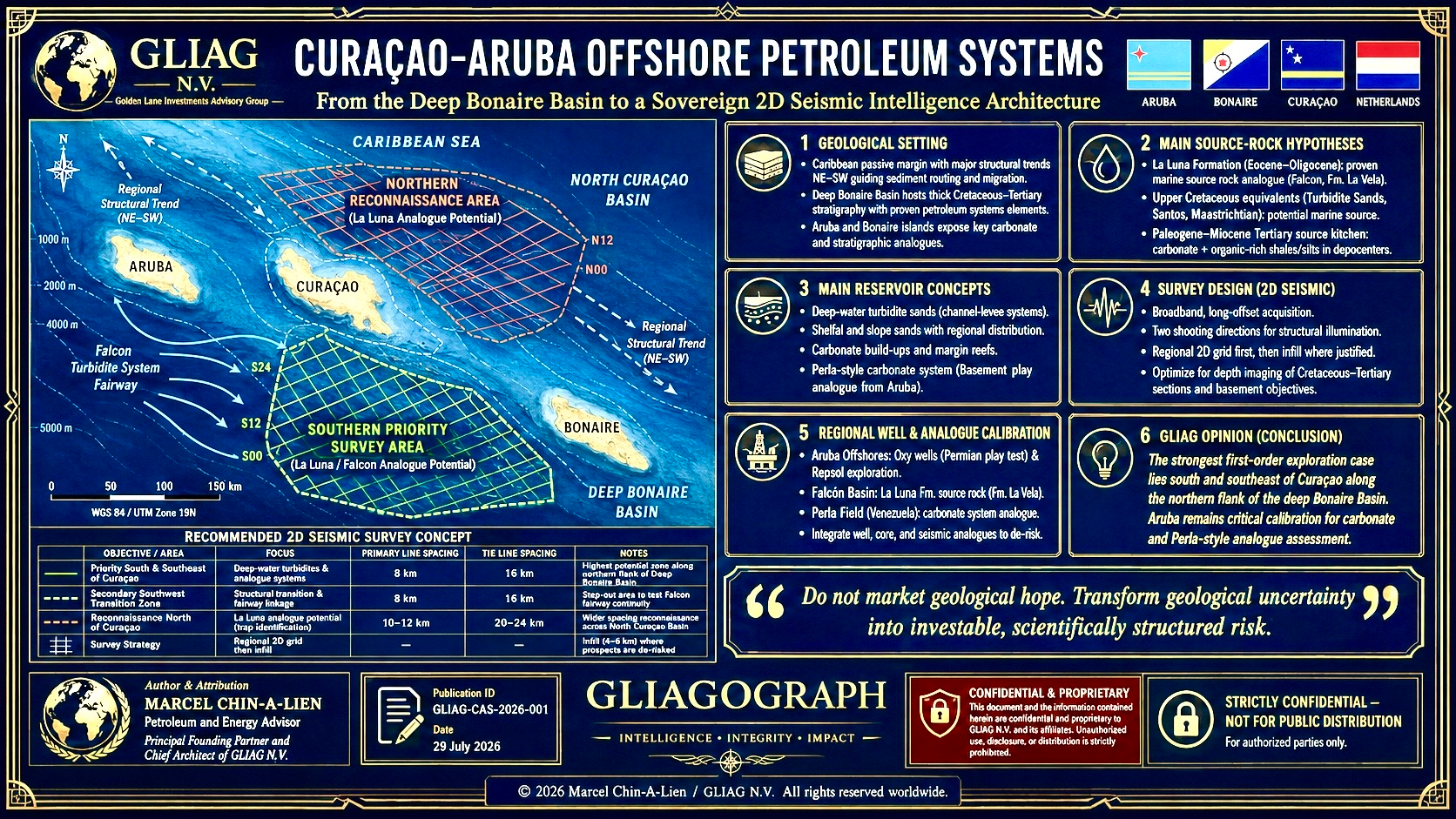
GLIAG Preliminary Offshore Curaçao–Aruba Seismic Design
Petroleum-systems architecture, acquisition parameters and regional calibration
I have prepared two preliminary technical figures:
These figures are exploration concepts, not navigational charts, maritime-boundary maps or final acquisition plans.
1. GLIAG executive opinion
The first survey should be concentrated south and southeast of Curaçao, crossing from the island-facing basin margin into the deepest practicable part of the Bonaire Basin.
That is presently the strongest location for testing a complete petroleum-system hypothesis:
deep Cenozoic kitchen → fault and carrier-bed migration → updip turbidite, shelfal or carbonate reservoirs → structural or stratigraphic trapping.
A smaller southwestern grid should test possible transition toward the Paraguaná–La Vela–Gulf of Venezuela petroleum province. The northern Curaçao offshore should initially receive only a reconnaissance grid because the sediment thickness, source presence and reservoir delivery systems remain materially less certain.
The recommended programme is therefore:
| Survey component | Strategic weight | Approximate line-km |
| Southern Curaçao–Bonaire Basin regional grid | 55–60% | 1,250–1,500 km |
| Southwestern Curaçao transition grid | 10–15% | 400–550 km |
| Northern Curaçao reconnaissance grid | 20–25% | 700–900 km |
| Long regional tie lines and well ties toward Aruba | 10% | 250–400 km |
| Initial regional programme | 100% | 2,600–3,350 km |
| Priority-fairway infill after interpretation | — | 1,800–2,700 km |
| Potential complete Phase I–II programme | — | 4,400–6,050 km |
Allowing approximately 10–15% operational line extension for run-in, run-out, turns, feathering recovery, obstacles and reshoots, the tender should provide an optional ceiling of approximately:
5,000–7,000 acquired line-km.
This does not mean that Curaçao should immediately acquire all 7,000 km. The regional phase should first identify whether a genuine kitchen, reservoir fairway and migration architecture coexist.
2. Recommended survey areas
Area A — Southern Curaçao and northern Bonaire Basin flank
Highest priority
The primary polygon should extend broadly:
- south and southeast from Curaçao;
- across the upper and middle slope;
- onto the northern and northwestern flank of the deep Bonaire Basin;
- far enough basinward to image the deepest accessible Cenozoic depocentre and possible source kitchen.
The Falcón–Bonaire system is interpreted as part of a complex Cenozoic basin province developed above Caribbean arc and plateau basement, affected by extension, strike-slip deformation and later inversion. Published work identifies fault-bounded basins involving Aruba, Curaçao, Bonaire, La Vela and the Gulf of Venezuela, but petroleum-system quality varies significantly between individual depocentres.
Main targets
- Paleogene–Neogene restricted marine source kitchens;
- basin-floor and slope turbidites;
- channel–levee complexes;
- sandstone pinch-outs;
- rotated fault blocks;
- inversion anticlines;
- flower structures;
- drape over basement or volcanic highs;
- carbonate platform-margin and mixed carbonate–clastic systems;
- migration along faults and regional unconformities.
Area A2 — Southwestern Curaçao transition
This smaller grid should test the geological transition toward:
- Paraguaná;
- La Vela Basin;
- the eastern Gulf of Venezuela;
- possible Miocene carbonate trends;
- Venezuelan continental-margin source systems.
It may be the most rational location to test a direct Perla-style carbonate gas analogue, although this remains unproven.
La Vela Basin studies document petroleum potential in early Miocene carbonate reservoirs and use extensive well and seismic calibration. The basin provides a much stronger analogue for southwestern Curaçao and eastern Aruba than the more distant Caribbean basins around Jamaica or Hispaniola.
Area B — Northern Curaçao reconnaissance
The northern grid should answer more fundamental questions:
- Is there a sedimentary basin of adequate thickness?
- Are Cretaceous sedimentary remnants preserved?
- Did Paleogene or Neogene restricted depocentres form?
- Were reservoir-bearing turbidites delivered into the area?
- Is the apparent structure sedimentary, volcanic or basement-controlled?
- Are source rocks thermally mature?
North Curaçao should not initially be promoted as a Perla or La Luna trend. The necessary source, reservoir and seal evidence is not yet established.
3. Recommended seismic grid geometry
3.1 Direction 1 — Basin-normal and structure-perpendicular
The principal lines south of Curaçao should run approximately:
NNE–SSW to NNW–SSE
The exact azimuth must be derived from legacy seismic, gravity, magnetics and bathymetry.
These lines should:
- cross the island margin and basin slope;
- cross the regional structural grain;
- image basin-bounding faults;
- establish sediment thickening;
- connect potential updip traps to deep kitchens;
- define shelf, slope and basin-floor depositional transitions.
They are the most important petroleum-system lines.
3.2 Direction 2 — Basin-parallel and longitudinal
The secondary family should run approximately:
WNW–ESE to ENE–WSW
These lines should:
- define closure length;
- track channel and fan continuity;
- map transfer faults;
- distinguish isolated fault blocks from regional ridges;
- constrain stratigraphic terminations;
- establish whether a structure has sufficient areal scale.
Two intersecting directions are essential because strike-slip and transtensional structures cannot be safely evaluated using a single 2D orientation.
4. Line spacing and the 500-million-barrel objective
Regional grid
Southern survey
- Main basin-normal lines: 8 km spacing
- Longitudinal ties: 16 km spacing
Southwestern transition
- Main lines: 8 km spacing
- Ties: 12–16 km spacing
Northern reconnaissance
- Main lines: 10–12 km spacing
- Ties: 20–24 km spacing
Infill grid
Where regional interpretation identifies a credible lead:
- Main infill lines: 4 km spacing
- Cross-lines: 4–8 km spacing
- Locally complex fault zones: approximately 2 km spacing
A 2 km grid should only be used selectively. It is not a substitute for 3D seismic.
Why this spacing is appropriate
A 500-million-barrel recoverable accumulation could require a productive area of approximately 75–250 km², depending on:
- net pay;
- porosity;
- saturation;
- formation-volume factor;
- column height;
- stacked reservoirs;
- recovery factor.
Illustrative screening cases are:
| Case | Productive area | Net pay | Porosity | Oil saturation | Recovery factor | Approximate implication |
| Thick compact structure | 75–100 km² | 70–100 m | 20–24% | 70–80% | 30–40% | Potentially material giant |
| Broad moderate-pay closure | 150–250 km² | 35–60 m | 18–23% | 65–78% | 25–35% | Potential 500 MMbbl-class |
| Stacked turbidite complex | 100–200 km² | 60–120 m aggregate | 20–27% | 70–82% | 25–40% | Potential giant if connected |
An 8 × 16 km grid can detect the regional geometry of structures of this scale, but it cannot confidently define spill points, fault compartments or subtle stratigraphic closure.
The correct sequence is:
Regional 2D identifies the play.
Infill 2D matures the lead.
3D seismic defines the prospect.
A well tests the petroleum system.
5. Highest-quality 2D acquisition specification
5.1 Survey type
The preferred acquisition is:
Deep-penetration, long-offset, broadband, true-amplitude, multi-client 2D marine seismic with simultaneous gravity and magnetics.
The survey should be designed to image:
- shallow Pliocene–Miocene carbonates;
- Paleogene and Neogene turbidites;
- deep source-rock kitchens;
- Upper Cretaceous intervals where preserved;
- basement and basin-bounding faults;
- deep detachments and strike-slip structures.
5.2 Indicative field parameters
An 8 × 16 km grid can detect the regional geometry of structures of this scale, but it cannot confidently define spill points, fault compartments or subtle stratigraphic closure.
The correct sequence is:
Regional 2D identifies the play.
Infill 2D matures the lead.
3D seismic defines the prospect.
A well tests the petroleum system.
5. Highest-quality 2D acquisition specification
5.1 Survey type
The preferred acquisition is:
Deep-penetration, long-offset, broadband, true-amplitude, multi-client 2D marine seismic with simultaneous gravity and magnetics.
The survey should be designed to image:
- shallow Pliocene–Miocene carbonates;
- Paleogene and Neogene turbidites;
- deep source-rock kitchens;
- Upper Cretaceous intervals where preserved;
- basement and basin-bounding faults;
- deep detachments and strike-slip structures.
5.2 Indicative field parameters
An 8 × 16 km grid can detect the regional geometry of structures of this scale, but it cannot confidently define spill points, fault compartments or subtle stratigraphic closure.
The correct sequence is:
Regional 2D identifies the play.
Infill 2D matures the lead.
3D seismic defines the prospect.
A well tests the petroleum system.
5. Highest-quality 2D acquisition specification
5.1 Survey type
The preferred acquisition is:
Deep-penetration, long-offset, broadband, true-amplitude, multi-client 2D marine seismic with simultaneous gravity and magnetics.
The survey should be designed to image:
- shallow Pliocene–Miocene carbonates;
- Paleogene and Neogene turbidites;
- deep source-rock kitchens;
- Upper Cretaceous intervals where preserved;
- basement and basin-bounding faults;
- deep detachments and strike-slip structures.
5.2 Indicative field parameters
| Parameter | Recommended specification |
| Streamer length | 12–15 km, subject to modelling |
| Record length | 16–18 seconds TWT |
| Sample interval | 1–2 ms |
| Group interval | approximately 6.25–12.5 m |
| Shot interval | approximately 18.75–25 m |
| Nominal fold | high fold, preferably 240–360+ depending geometry |
| Source | tuned broadband air-gun array with low-frequency output |
| Navigation | differential GNSS with full streamer positioning |
| Additional acquisition | gravity, magnetics and high-resolution bathymetry |
| Near-field hydrophones | required |
| Source signature | measured and retained |
| Processing objective | phase-preserved, amplitude-compliant PSTM and selected PSDM |
Streamer length and source parameters must be tested through illumination modelling, particularly where steep volcanic basement or carbonate velocity contrasts occur.
6. Frequency design and direct hydrocarbon indicators
Recommended bandwidth objective
The acquisition and processing should target a usable bandwidth approximately:
2.5–100 Hz, with an aspirational processed range of 2–120 Hz where signal-to-noise permits.
Streamer length and source parameters must be tested through illumination modelling, particularly where steep volcanic basement or carbonate velocity contrasts occur.
6. Frequency design and direct hydrocarbon indicators
Recommended bandwidth objective
The acquisition and processing should target a usable bandwidth approximately:
2.5–100 Hz, with an aspirational processed range of 2–120 Hz where signal-to-noise permits.
The most important ranges are:
| Frequency band | Principal purpose |
| 2–8 Hz | Deep penetration, velocity model building, FWI, broad carbonate and basin architecture |
| 8–25 Hz | Deep structures, source kitchens, large turbidite complexes |
| 20–60 Hz | Reservoir-scale architecture and most conventional bright-spot analysis |
| 50–100+ Hz | Shallow stratigraphy, thin beds and detailed carbonate or channel geometry |
The exact vertical resolution depends on interval velocity.
For a Tertiary clastic interval with velocity near 2,500–3,000 m/s:
- 25 Hz gives a dominant wavelength of approximately 100–120 m;
- practical quarter-wavelength resolution is approximately 25–30 m;
- 50 Hz may resolve approximately 12–15 m under favourable conditions.
For carbonates with velocities of 4,000–5,000 m/s, vertical resolution will be materially poorer at the same frequency.
Requirements for flat spots and bright spots
The data should be processed for:
- zero-phase or consistently known phase;
- true relative amplitude preservation;
- source and receiver deghosting;
- designature and deterministic wavelet control;
- spherical-divergence correction;
- absorption and Q compensation;
- surface-related multiple elimination;
- interbed multiple attenuation;
- anisotropic velocity analysis;
- tomographic depth-model building;
- full-waveform inversion where possible;
- pre-stack angle gathers;
- AVO-friendly processing;
- spectral decomposition;
- frequency-dependent amplitude analysis;
- diffraction imaging;
- selected least-squares migration.
Critical limitation
A flat spot or bright spot on a 2D line is not proof of hydrocarbons.
In the Curaçao–Aruba setting, apparent amplitude anomalies may result from:
- out-of-plane energy;
- volcanic or intrusive bodies;
- carbonate velocity contrasts;
- tuning;
- multiples;
- acquisition footprint;
- fault-plane reflections;
- side-swipe;
- residual depth error.
A DHI observed only on one 2D line should be treated as a lead-supporting observation, not a prospect-level risk reducer. Confirmation should require intersecting lines, rock-physics consistency and ultimately 3D seismic.
7. Conceptual stratigraphic and petroleum-system architecture
South Curaçao and Bonaire Basin
| Interval | Possible lithology and play | Petroleum-system role |
| Quaternary–Pliocene | reef carbonates, slope debris, shallow marine sediment | Shallow reservoir or overburden; biodegradation risk |
| Late–middle Miocene | slope channels, basin-floor fans, shoreface sands, fine clastics | Principal clastic reservoir; possible secondary source and seal |
| Early Miocene | carbonate platforms, build-ups, mixed clastic-carbonate systems | Possible Perla/La Vela-age reservoir; local seal |
| Oligocene–Eocene | syn-rift shale, turbidites, restricted marine sediment | Strongest possible Tertiary source-kitchen interval; reservoir locally |
| Upper Cretaceous | local marine sediment or La Luna-age equivalent | Possible oil-prone source, but continuity is unproven |
| Basement | volcanic, oceanic-plateau, intrusive and metamorphic rocks | Structural control; generally non-source |
The Falcón–Bonaire basin system developed above complex basement and contains Cenozoic fault-bounded basins, making Tertiary self-sourced systems at least as important as a presumed La Luna system.
North Curaçao
| Interval | Possible lithology and play | Confidence |
| Neogene | deep-water clastics and local carbonates | Low–medium |
| Paleogene | fault-bounded marine depocentres | Low |
| Upper Cretaceous | preserved arc-basin sediment or organic-rich remnants | Very low |
| Basement | Caribbean oceanic and arc-related crust | High |
| Source maturity | unknown | Very low |
| Reservoir delivery | unknown | Very low |
The north requires reconnaissance to establish the existence of a viable sedimentary basin before more detailed petroleum claims are made.
Aruba–Falcón–Perla trend
Chuchubi-1 penetrated a predominantly carbonate succession from early Pliocene through Oligocene and possibly late Eocene, reaching approximately 9,210 ft. Fourteen maximum-flooding surfaces were identified between about 4 and 35–36.5 Ma, and the interpreted paleobathymetry deepened from neritic to bathyal or abyssal conditions.
That well proves a thick Cenozoic section offshore Aruba. It does not prove commercial porosity, effective charge or a Perla analogue.
8. Aruba well inventory and implications
| Well | Operator | Approximate year | Publicly reported result | Implication |
| Mero-1 | Historical operator requires primary verification | 1989 reported | Public technical details not recovered | Confirms historical shallow offshore campaign; file recovery required |
| Divi Divi-1 | Historical operator requires primary verification | 1989 reported | Public technical details not recovered | Same; result should not be inferred |
| Chuchubi-1 | Occidental/Oxy | circa 1990 | 9,210 ft; thick Pliocene–Oligocene/possible Eocene carbonate section | Strong stratigraphic calibration; source and charge unresolved |
| Fourth historical Aruba location | Operator and well name not verified | Historical | Government states four locations were drilled without commercial success | National archive gap |
| Bon Bini-1 | Repsol/partners, reported name requiring operator-file confirmation | 2018 | Government subsequently stated Repsol attempts found nothing; detailed well result unavailable | Modern failure mode must be established before ranking acreage |
The Aruba government stated in 2024 that drilling had previously occurred at four locations in territorial waters with little success, and that Repsol attempts did not result in a discovery. It also confirmed that Armstrong’s initial work would be geological and geophysical, with the aim of identifying new drilling locations.
Repsol contracted the West Capella for one Aruba exploration well in 2018. The available public sources confirm the drilling contract but do not provide a complete authoritative well report.
Consequence for Curaçao
The Aruba wells demonstrate that:
- thick Tertiary sediment is present locally;
- carbonates may be widespread;
- previous prospect failure does not automatically condemn the regional petroleum system;
- source, migration, seal and precise structural positioning remain the critical unknowns;
- Curaçao should obtain and reinterpret the complete Aruba well dataset before finalising its survey.
9. Venezuelan and Maraven offshore wells
A complete public-domain register of all Venezuelan offshore wells between Aruba, Curaçao and the mainland is not available. PDVSA, Maraven, Corpoven and predecessor-company archives must be accessed to produce an auditable well-by-well catalogue.
The verified Maraven campaign described by AAPG comprised:
- 3 wells in Golfo Triste;
- 12 wells in the Tuy–Cariaco Basin;
- 15 wells in total between 1978 and 1982;
- no economic discoveries;
- hydrocarbon indications in MTC-1X and EBC-1X.
The campaign used approximately 19,200 km of legacy 2D seismic in Tuy–Cariaco. Later geochemical interpretation suggested that much of the Pleistocene–Eocene section drilled there lacked sufficient kerogen-rich material for major generation. The AAPG account nevertheless concluded that deeper slope turbidites and modern 3D seismic could justify renewed investigation.
Named wells publicly identified
| Well | Basin/area | Result | Consequence |
| MTC-1X | Tuy–Cariaco | Hydrocarbon indications, non-commercial | Demonstrates limited charge or shows; does not prove a commercial system |
| MTC-2X | North Tortuga–Margarita Shelf | No commercial accumulation reported | Helps constrain shelf stratigraphy and basement |
| EBC-1X | Ensenada–Barcelona Shelf | Hydrocarbon indications, non-commercial | Evidence of migration but insufficient accumulation |
| CMA-1 | Cubagua–Margarita Shelf | No commercial result reported | Calibrated shelf stratigraphy and basement |
These wells lie considerably east of Curaçao and Aruba. They are useful primarily as analogues for exploration failure modes, source deficiency and deep-water under-testing—not as direct well control for the Bonaire Basin.
More relevant Venezuelan datasets still required
The following must be obtained from PDVSA and historical subsidiary archives:
- Corpoven La Vela offshore wells;
- Gulf of Venezuela wells;
- Paraguaná shelf wells;
- Golfo Triste wells;
- Cardón IV exploration and appraisal wells;
- La Vela 52-well database;
- Maraven, Lagoven and Corpoven regional seismic;
- former Shell, Creole, Oxy, Mobil and Texaco offshore studies.
10. Perla comparison
Perla proves that Lower Miocene carbonates in the Gulf of Venezuela can contain a giant gas accumulation with excellent petrophysical properties. Eni has publicly described Perla as a Miocene carbonate reservoir and has used it as an analogue in other giant carbonate-gas exploration concepts.
A defensible Perla analogue offshore Aruba or Curaçao must contain:
- a thick Lower Miocene or age-equivalent porous carbonate;
- a large closed structure or sealed stratigraphic body;
- a credible gas source;
- migration access;
- an effective regional seal;
- correct timing;
- preservation through later faulting and uplift.
Best locations
Aruba
The strongest Perla-analogue search should focus on:
- southeastern and southern Aruba;
- carbonate margins adjacent to deeper Gulf of Venezuela or Paraguaná-related depocentres;
- northeastern Aruba only after Chuchubi-1 and Bon Bini-1 are fully reinterpreted.
Curaçao
The most plausible direct Perla-style area is:
- southwestern Curaçao, where Miocene carbonate bodies might approach Venezuelan-margin petroleum systems.
The strongest overall Curaçao petroleum target is nevertheless farther southeast toward the Bonaire Basin, where the principal reservoirs may be turbidites or mixed clastic-carbonate systems rather than a Perla duplicate.
Curaçao may contain a Perla-scale accumulation without containing a Perla-type reservoir.
11. Source-rock hierarchy
| Candidate source | Location | Confidence | GLIAG interpretation |
| La Luna Formation | Northern Venezuela/Maracaibo–Falcón regional system | Proven regionally | Strong oil source, but continuity beneath ABC islands is unproven |
| Upper Cretaceous local marine equivalents | Offshore ABC arc-related basins | Low | Must be proven; should not be labelled La Luna without samples |
| Pecaya-type marine shale | Falcón–Bonaire system | Medium | Important possible Tertiary source |
| Agua Clara-type marine shale | Falcón–La Vela system | Medium | Possible source and seal |
| Oligocene–Miocene restricted basin shale | Deep Bonaire Basin | Medium conceptual | Strongest southern Curaçao kitchen hypothesis |
| Miocene marine and deltaic shale | Basin margins | Medium–low | Mixed Type II/III oil and gas source |
| Shallow microbial gas source | Gulf of Venezuela-type settings | Possible | Relevant to Perla-style gas charge |
The La Luna Formation is a major northern South American petroleum source, but regional source-rock importance does not demonstrate physical continuity beneath Curaçao or Aruba.
12. GLIAG recommendations
Immediate Phase 0
Before tendering the survey:
- Recover all Curaçao, Aruba, Bonaire and Venezuelan legacy navigation and seismic.
- Obtain the Oxy, Repsol and CAP well files.
- Acquire all available La Vela, Cardón IV and Paraguaná regional studies.
- Create an integrated gravity–magnetic basement map.
- Undertake satellite seep screening and bathymetric geomorphology.
- Reprocess representative legacy lines before finalising azimuths.
- Conduct source–reservoir–seal common-risk mapping.
- Perform environmental exclusion screening.
Phase I
Acquire approximately 2,600–3,350 km of broadband regional 2D.
Phase II
Infill only the best petroleum-system fairways with an additional 1,800–2,700 km.
Phase III
Acquire 3D seismic over no more than two or three leads that demonstrate:
- material structural or stratigraphic scale;
- plausible reservoir;
- source maturity;
- migration access;
- seal;
- correct timing.
13. Final GLIAG opinion
The geological justification for a modern offshore Curaçao survey is credible.
The most defensible case is not based on the claim that La Luna must extend beneath Curaçao, nor that every Miocene carbonate is another Perla.
It rests on a broader and stronger proposition:
- the deep Bonaire Basin may contain mature Tertiary source kitchens;
- the basin margin may contain deep-water turbidite and carbonate reservoirs;
- multiphase extension, strike-slip deformation and inversion may have created large traps;
- petroleum may have migrated updip toward southern Curaçao;
- Aruba proves that a thick Cenozoic carbonate succession exists within the ABC offshore region;
- Venezuela proves that multiple Cretaceous and Tertiary petroleum systems operate nearby.
The survey should therefore be designed to discover the petroleum-system architecture, not merely attractive structures.
The first objective is not to find a bright spot. It is to prove the relationship between kitchen, migration, reservoir, trap, seal and preservation.
GLIAG’s preferred allocation remains:
- 60–70% south and southeast Curaçao;
- 10–15% southwest Curaçao;
- 15–25% north Curaçao reconnaissance.
Principal researched publications and sources
- AAPG, Maraven’s Tuy–Cariaco Exploration Campaign: 15 wells, seismic history, named wells and campaign results.
- Search and Discovery/AAPG, Chuchubi-1 Offshore Aruba Sequence Stratigraphy.
- GeoScienceWorld, Subsurface Geology of La Vela Basin.
- GeoScienceWorld, Falcón–Bonaire and Leeward Antilles tectonic framework.
- USGS publications on the La Luna petroleum source system.
- Government of Aruba, CAP–Andicuri/Armstrong agreement and exploration status.
- Repsol/Seadrill-related reporting, 2018 Aruba drilling programme.
- Eni technical material referencing Perla as a Miocene carbonate gas reservoir.
- Aruba geology report acknowledging Armando Curet, then Director of Compañia Arubano di Petroleo, as a geological contributor. This report is general onshore geology and does not contain a complete offshore petroleum interpretation.
Strict disclaimer, copyright and proprietary-rights notice
Geological, geophysical and exploration disclaimer
This document is a preliminary, conceptual and independent strategic petroleum-intelligence assessment. It is not a certified resource or reserve report, competent-person report, securities disclosure, investment memorandum, licence application, environmental-impact assessment, navigational chart, maritime-boundary determination, acquisition-ready seismic programme or drilling recommendation.
The maps, survey polygons, line orientations, line spacing, stratigraphic columns, volumetric examples and petroleum-system interpretations are conceptual and have been prepared from publicly accessible regional information and professional geological reasoning. Coordinates, coastlines, boundaries, basin outlines and line positions are approximate. No representation is made that the depicted areas are legally available, environmentally permissible, free from infrastructure, technically safe or situated entirely within Curaçaoan or Aruban jurisdiction.
No hydrocarbons, recoverable resources or reserves are asserted to exist. References to 500-million-barrel-class structures describe a survey-design objective and possible trap scale, not discovered or prospective resources. Direct hydrocarbon indicators, including bright spots and flat spots, are non-unique and may result from lithological, processing, acquisition or velocity effects.
All interpretations must be verified through access to original field data, seismic navigation, well files, cores, cuttings, logs, laboratory analyses, environmental studies, maritime-boundary information, modern processing, 3D seismic and drilling.
Copyright, intellectual property and proprietary notice
© 2026 Drs. Marcel P. T. Chin-A-Lien, MBA, M.Sc., Ing., CPG (AAPG), EurGeol (EFG) and GLIAG N.V. — Golden Lane Investments Advisory Group. All rights reserved worldwide.
The title, structure, survey concept, line-grid architecture, geological synthesis, petroleum-system framework, source–reservoir–seal analysis, Perla-analogue screening, strategic conclusions, maps, figures, tables, terminology, prioritisation logic and associated recommendations constitute proprietary intellectual property.
No part may be copied, reproduced, republished, translated, adapted, distributed, transmitted, disclosed, commercially used, incorporated into a licence proposal, tender, seismic programme, investor presentation, government submission, data-room product, technical report, model or derivative work without prior express written permission from Drs. Marcel P. T. Chin-A-Lien and GLIAG N.V.
Receipt or review of this material does not transfer ownership, grant a licence, establish a partnership, create an advisory mandate or authorise reliance. Any authorised use must preserve the complete attribution, copyright, disclaimer and proprietary-rights notice.
Author and institutional identification
Drs. Marcel P. T. Chin-A-Lien, MBA, M.Sc., Ing.
Certified Petroleum Geologist — AAPG
European Geologist — EFG
Principal Founding Partner & Chief Architect
GLIAG N.V. — Golden Lane Investments Advisory Group
Zoetermeer, the Netherlands / Paramaribo, Suriname
Website: petroleumenergyinsights.com